I just finished a complete rebuild of the front suspension and steering on our 1984 Eagle wagon. I had two main goals when I started collecting parts: I wanted to incorporate alternatives for the obsolete tie rods and ball joints, and I wanted to make the bushings and bearings greasable.
Because I only had two days to do the rebuild, I collected an entire second Eagle front suspension to have things prepped before hand. The only parts I reinstalled in the process were the springs and steering idler arm (all of which I replaced in 2019).
Here’s a breakdown of parts I used:
Lower Control Arm bushings Energy Suspension 3.3167G (see notes on bushings)
Upper Control Arm Bushings Prothane 1-208
Sway bar bushings ENERGY SUSPENSION 95162G
Sway bar end links ENERGY SUSPENSION 98175G
Coil Spring Isolator Prothane 1-1704
Spring perch bushings Energy Suspension 4.2132G
Strut rod bushings Prothane 6-1205
Shocks Monroe 5756
Upper ball joints Moog K3082
Lower ball joints Rare parts 10492
Inner tie rods MEVOTECH MES381RL
Outer tie rods MEVOTECH MES323L
Tie rod Adjuster MEVOTECH MES350S
Wheel bearings Timken Set26
Hub seal Timken 3942
Hub o-ring Miller J3238141
Knuckle seal Timken 3553
HardwareZerks Performance Tool W54217 and McMaster 1059K73
Wheel Studs DORMAN 610256
Ball joint mounting hardware McMaster 91286A182, 91286A185, 91263A187, 94820A240
Hub carrier mounting bolts McMaster 93700A229
Hardware for caliper bracket, steering arm, and strut rod to control arm McMaster 90602A236, 90602A233, 90602A234, 94820A249
Shock brackets McMaster 91627A116, 90602A217
Control arm modifications and bushingsI decided I wanted polyurethane bushings over rubber. I prefer the predictability and durability of polyurethane over rubber suspension bushings. The main challenges were the lower control arm and spring perch bushings. I found that mustang guys install poly lowers with a similar strut-rod-style suspension, so I decided I’d try it. Since our rubber bushing cross references for tons of GM cars, I bought a kit for a late 70s Chevy Nova that had poly bushings and new bushing shells. The smaller bushing pair fit perfectly and the shell pressed into the eagle control arm nicely.


I welded in angle iron as reinforcement on the lower control arms and spring perches to eliminate the fear of bending anything on the press. The reinforcement made it much tougher to get to the shock studs on the spring perch.
I pressed the spring perch bushings apart, but I would burn them out in the future and avoid welding in the angle iron. I found on another AMC forum that Ford truck leaf spring bushings will work in the spring perch bushing shell and fit the old bushing shaft. The original shell is tapered, so I pressed a socket through to help open the small side for the bushings.
One issue I had to address was the combo of the poly lower control arm and strut rod bushings. There are reports on the mustang forums of their strut rods snapping from the binding of the two poly bushings, especially if the washers have the concave side in. I flipped the washers on the bushings to lessen the stiffness and made sure the strut rod could move without severe binding. With the concave side of the washers in, I could hardly torque the strut rod bushings to 65ftlbs, and when I did they would not budge. After flipping the washers concave side out, the bushings torqued easily and were much easier to move.
One issue with poly bushings is they have to be greased if they are going to last. I drilled and tapped all of the bushing shells for grease zerks. On the lowers, I used 65° zerks from Mcmaster Carr and ground the adapter so it was flush with the interior of the busing shell when installed.

I did the same on the uppers. Due to the thinness of the shell, there isn’t a lot of meat for threads of the zerk (the exception being the one upper bushing with the retainer ring.

I put the zerk through that and it was perfect. If I were to do it again, I would add ¼-28 weld nuts to the other bushing shells for peace of mind. On the spring perch, there is empty space between the two bushings, so I just ran the zerk in until it was fully seated against the shell. I did have to wait to install the zerk until after the shock was in place so it wasn’t in the way of torquing the shock nuts.
In order to get the grease to the inner sleeve where it should be, I ground a shallow groove around the outside of each bushing that aligned with it’s zerk and then drilled 8 holes to the grease grooves on the inside of the bushing.

The modifications Seem to be working well, and if the groove compromises the bushing integrity, they are super easy to replace.

Here's a pic of the zerk in action
 Ball Joint clearance
After finding Ludworks youtube video, I started investigating the interference issues on the Rare Parts lower ball joints. Because the RP lowers are the same as the moog uppers with a taper adapter (part#), I separated the added reinforcement plate and sandwiched the lower control arm between the plate on top and the ball joint body on bottom. I had to modify the reinforcement plate to fit over the raised section of the control arm, by widening the central hole with a hole saw. I also ground the steering arm slightly where it rubbed the reinforcement plate.

In hindsight, I should have just ground that raised section off since I doubt it adds much over the reinforcement plate. I then countersunk the rear outer bolt hole for a flat head bolt and ground the steering arm lightly to eliminate the interference between the steering arm and ball joint reinforcement plate at full compression.

This meant that I did use a grade 5 bolt in that spot, but the remaining lower ball joint hardware is grade 8 and the setup isn’t in tension while driving down the road. I ground the rear outer edge of the lower control arm itself since it was clear it had been rubbing even with the factory ball joints. I also used my taper reamer to clean up and slightly deepen the hole on the bottom of the knuckle. This raised the knuckle relative to the control arm and helped with the clearance issue on the steering arm. This also created enough clearance for me to run 90° zerks on the lower ball joints without rubbing the CV boots. (The supplied moog 90° zerks are too tall. I had to use the ones in a Performance Tool variety pack since they are shorter).
In terms of parts availability, I can now order moog upper ball joints, install the tapered spacer, and have a cheap replacement for the lower units. I think the Ludworks solution with the Jaguar lower ball joint is probably superior to my setup and requires far less work once the control arm modifications are done.
I did have to trim the front outer lower ball joint bolt because it rubbed the knuckle when turning. I simply trimmed it flush with the flex-top locknut and that seems to be enough.
Hub RebuildI rebuilt the hubs using my AMC hub service kit (#8980002647).

It makes the process very quick. I decided to drill both hub carriers for grease zerks. I had to angle the zerks to be perpendicular to the hub carrier surface so that they wouldn’t interfere with the hub carrier mounting flat to the knuckle. I drilled one hub by hand and one in a drill press…use a drill press. I also pressed in new wheel studs since I had the hubs apart for sandblasting.

You can see the hub zerk on this photo

Using a shop press and the factory tools makes this job a breeze. I can rebuild a set of hubs in about an hour if I’m focused. Here’s the order I follow
Disassembly: Press out hub, remove inner bearing, press bearing races out of carrier, press hub out of outer bearing, remove wheel studs (optional
Assembly: Press new races into carrier


Pack and install outer bearing.

Install hub seal 3942


Press hub into carrier through bearing and seal, press on inner bearing
Don’t forget the washer for the CV preload
 Steering Modifications
I wanted to find a more readily available steering setup and decided to ream the steering for larger chevy parts. I did this off of the car; there isn’t enough room to get a drill on the reamer for the central link holes with the central link installed in the car. I reamed it a little at a time and aimed to have the tie rod taper as deep as possible while still having a few threads on the studs to pull it tight into the central link and knuckles.

An added bonus is the adjustment threads on the chevy tie rod ends are bigger than the AMC parts.

Here's a shot of the new center link and Chevy tie rod ends next to the original Eagle parts.

I always had an issue with the stud of the passenger tie rod end scraping against the flange of the K-member. I think the flange was bent up at some point so I tried to bend it as flat as I could get it. I ended up trimming the end of one of the new studs to avoid the interference. I probably could enlarge the taper on the idler arm hole to help raise that end of the central link a hair, but it’s fine for now.
PrepAll of the suspension parts were sandblasted and coated with Mastercoat’s Permanent Rust Sealer and AG111 Chassis Finish. I brushed on both products, and while the sealer leveled nicely, the AG111 was too thick and left a brush texture. I will buy their thinner before I use it again.
I also replaced all of the hardware (bolts, etc.) with new grade 8 parts from Mcmaster Carr with the exception of the control arm bolts. This allowed me to get rid of the external torx fasteners.
I had a complete second set of suspension parts ready to assemble since I only had 2 days to do the rebuild. I do have a factory-style spring compressor and would not recommend doing this job with a parts-story style compressor. (Did that once and it was terrifying)
DisassemblyI pulled the sway bar end links and shocks with the eagle sitting on the ground. I then blocked the upper control arms according to the FSM and lifted the eagle so the front tires were off the ground. I pulled the tires, calipers, pads, and rotors. I then pulled the front CV axles. At this point I broke all the bolts and nuts loose on the ball joints, strut rods, tie rod ends, caliper brackets, and steering arms. It’s way easier to put serious torque on fasteners while everything is assembled. If you’re pulling the control arms, hub, and knuckle as an assembly like I did, skip the next paragraph.
Next, separate the tie rod from the steering arm and completely remove the steering arm and caliper brackets from the knuckle. Break loose the hub carrier bolts and pull the hub. An axle puller and slide hammer will take care of the hub if they’re stuck in the knuckle, or you can thread the bolts back in and knock on them from the backside to work it out. Pull the strut rod nuts and rear bushing before separating the strut rod from the lower control arm. Separate ball joints from the knuckle. Remove the knuckle.
Disconnect the lower control arm bolt and remove the lower. Install the spring compressor in place of the shock and compress the spring.
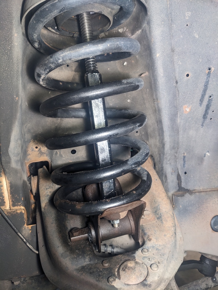
Remove the spring-perch-to-upper-control-arm bolts and then remove the upper control arm bushing bolts. At this point, you have to compress the spring enough to get the upper control arm out from under the retracted spring and perch. The only remaining step is to release the spring compressor to free the perch. The perch will want to snag on the uniframe as it comes down. I put a piece of sheetmetal over the lip of the front rail there to help it slide down along the side without scraping the uniframe.

Remove the old ball joints from the control arms by grinding the rivets flush and punching them through the control arms.
Repeat the process for the other side.
To pull the center link (if reaming for larger tie rods) I had to pull the steering damper off of the center link stud and separate the idler and pitman arm tapers. I had to go back and forth from lock to lock to get access to the different studs and tapers for the job and used a “Front End Service Kit” from Advanced Auto that had several pullers and separators in it. I removed the idler arm completely and then threaded the center link, with the tie rods attached, out through the driver side.
InstallReam the steering arms and center link for the new tie rods (if applicable) and reinstall the center link with new tie rod ends. Check for any rubbing on studs. Don’t forget to replace the knuckle seals.

I assembled the ball joints on the control arms; pressed the new lower shells in; and installed bushings on uppers, lowers, and spring perches. I installed the upper coil spring isolator. Then I reinstalled the spring compressor on the spring and perch and compressed the spring enough to get the upper control arm into position.

This was a two man job to get the upper control arms in place and the bolts torqued to spec, especially on the driver side. I used my extension wrenches, but my engine bay is super tight with the EFI swap.
With the upper control arms bolts in place, I bolted it to the spring perch, blocked the upper control arm, and released the spring before removing the compressor. Next I installed the shock, lower control arm, knuckle, and strut rod. Then I installed the dust shield and hub assembly in the knuckle.
A quick note: The strut rod bolts and lower ball joint can get in the way when torquing the hub bolts and other hardware. I used my flexible adapters and didn’t have an issue, but others might want to install the dust shields and hubs on the knuckles while the knuckles are off of the car and then assemble the steering arm and caliper bracket to the knuckle before putting the strut rods in.
Then I installed the caliper bracket and steering arm before attaching the outer tie rod end. I installed the CV axle, brake rotor, and caliper before repeating the entire install process on the other side. After both sides are done, I replaced the sway bar bushings. I did have to run a tap into the frame brackets to clean out the holes for the sway bar bushing brackets. Lastly, I installed the new sway bar end links before filling all of the bushings with Prothane grease and the ball joints and tie rod ends with Spicer Extreme Pressure grease. With eagle back on its tires, I pulled the wooden blocks from under the upper control arms.

A quick trip to the alignment shop, and the Eagle drives better than it ever has. I checked the torque of all the fasteners the following weekend.
I was under the gun to get this thing done, so I didn't take pictures of every step, but if anyone has questions or wants other pictures of the parts installed, I can probably grab some more.

 Topic: Complete Front Susupension Rebuild with Parts List and Pictures (Read 277 times)