News: Putting FUN and FRIENDLINESS, FIRST into owning and learning about AMC small bodied cars, primarily Eagles, Spirits and Concords as well as vehicles built in AMC's Mexican subsidiary, VAM.

The AMC Eaglepedia can now be accessed using the buttons found below  This is a comprehensive ever growing archive of information, tips, diagrams, manuals, etc. for the AMC Eagle and other small bodied AMC cars. 

Also a button is now available for our Face Book Group page.


Welcome to the AMC Eagles Nest.  A new site under "old" management -- so welcome to your new home for everything related to AMC Eagles, Spirits and Concords along with opportunities to interact with other AMC'ers.  This site will soon be evolving to look different than it has and we will be incorporating new features we hope you will find useful, entertaining and expand your AMC horizons.

You can now promote your topics at your favorite social media site by clicking on the appropriate icon (top upper right of the page) while viewing the topic you wish to promote.


  • May 13, 2024, 01:11:54 PM

Login with username, password and session length

Author Topic: ECM Test Bypass Help  (Read 21095 times)

0 Members and 1 Guest are viewing this topic.

Prafeston

  • Guest
ECM Test Bypass Help
« on: January 27, 2012, 06:24:59 PM »
1983 AMC Eagle Limited

I'm trying to follow directions given by GRONK and also some charts and directions found online here:
http://www.amceaglesden.com/~iowaeagl/guide/index.php?title=Diagnostic_ECM_Test


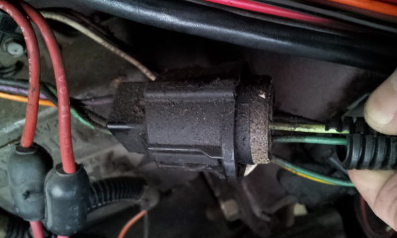
It looks like I'm supposed to be taking the Orange and Purple Wires from the Distributor and Splicing them straight into the Ignition Module(IM). I don't see a problem with the purple one as I see from the diagram the purple wire leaves the IM, but it only goes to the plug and then disappears so you just splice it in right there in that area between the IM and the plug.


The diagram shows the that you splice in at the firewall, but the orange wire that leaves the IM also disappears at the plug like the purple one does. So can I splice both of the wires in before the plug? The three wires leaving the plug are black, green, and light green. Like it shows in the diagram for the '86 model.

'86 Diagram


So how do I need to go about this? Seems like the most logical thing would be to splice the orange wire in before the plug just like you do with the purple one.

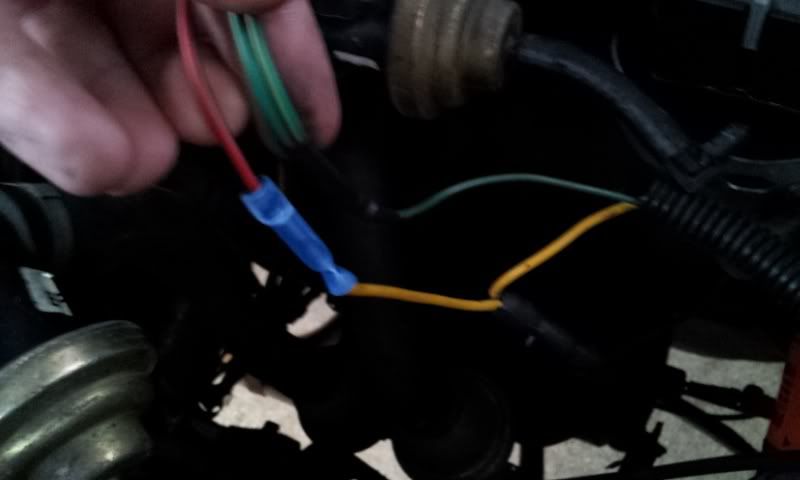
Also in GRONK's instructions you are also supposed to splice into the the Ignition Coil(IC) before and after the resister in the red wire. Well, the wire that came with GRONK's kit is red, but the wire I had to splice into is yellow. That wire goes into what looks like a resistor and another yellow wire goes comes out and goes to a ground. So GRONK's kit has a red wire and a green wire(actually two green wires) and the stock IC had a yellow and a green wire. Did I hook this up right going green to green and red to yellow?


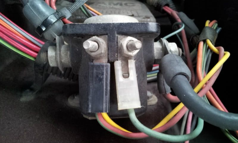
GRONK's diagram also shows that you'll be splicing in the red wire from the Starter Solenoid(SS) into that red wire leaving the IC, but my SS has a red wire with green stripe and yellow wire leaving the same connection with the green wire on the other connection. So I'm not really sure which wire should be spliced.


Then again on GRONK's diagram I'm supposed to splice the red wire from the IM into the red wire leaving the resistor from the IC (which in my case is yellow), but the red and white wires leaving the IM go to a plug and then turn into yellow and green wires. In general I'm just quite confused about what I'm supposed to be doing since none the the wires seem to be the same color as what's in the diagrams.

« Last Edit: May 11, 2020, 08:54:17 PM by Taylor »

Offline ammachine390

  • Eagle Limited
  • *****
  • Posts: 722
  • Thumbs Up 42
Re: ECM Test Bypass Help
« Reply #1 on: January 27, 2012, 06:56:32 PM »
I assume you are also dong the TFI/MIU upgrade, using a pertronix ignition coil. I'm a little confused about what you spliced into your ignition coil. When I did the MIU upgrade, I cut the yellow wire on the starter solenoid, and then spliced it into the yellow wire on the harness side of the 2 wire plug for the ignition module. That will bypass the ignition resistor (unrelated to the computer bypass).

http://www.amceaglenest.com/images/Eaglebook/MIU.pdf
Dan
1981 AMC Concord DL 258 Auto

Click for Villa_Park, IL Forecast" border="0" height="100" width="150

Prafeston

  • Guest
Re: ECM Test Bypass Help
« Reply #2 on: January 27, 2012, 07:22:36 PM »
I assume you are also dong the TFI/MIU upgrade, using a pertronix ignition coil. I'm a little confused about what you spliced into your ignition coil. When I did the MIU upgrade, I cut the yellow wire on the starter solenoid, and then spliced it into the yellow wire on the harness side of the 2 wire plug for the ignition module. That will bypass the ignition resistor (unrelated to the computer bypass).

http://www.amceaglenest.com/images/Eaglebook/MIU.pdf

I did the TFI(Ignition Coil) upgrade from GRONK. His kit comes with a plug that plugs into the new coil. That plug had 2 green wires and one red wire.

Prafeston

  • Guest
Re: ECM Test Bypass Help
« Reply #3 on: January 27, 2012, 07:25:54 PM »
Thanks for the link Regal!

Prafeston

  • Guest
Re: ECM Test Bypass Help
« Reply #4 on: January 28, 2012, 05:00:27 PM »
Ok, I still need some help here.

I did this bypass orange/orange and purple/purple and now the car will start, but will only run when I've got the key still pushed forward in the start position. As soon as I put it in On after starting it cuts off...but then when I turn the key to Off it acts like it was still kind of running and I can hear it power down.

What have I done wrong? There is still the IC and SS splicing that it seems like I need to do juding by the pdf of GRONK's. I've tried calling and texting GRONK, but I'm getting no response and his voicemail box is full. He is a busy man!

Need some help! AHHh

Offline IowaEagle

  • AMC Eagle Archivist
  • Administrator
  • AMC Eagles Den Addicted
  • *****
  • Posts: 31968
  • Thumbs Up 476
Re: ECM Test Bypass Help
« Reply #5 on: January 28, 2012, 05:19:36 PM »
Jurgen is an expert on this too.
Click for Toledo, IA Forecast" border="0" height="100" width="150   


Not a Jeep.  Not a Car.  Its an AMC Eagle!

1982 Eagle SX/4 Sport;
1980 Concord DL;
1970 Ambassador 2 Dr HT, SST
2002 Hyundai Santa Fe;
2008 Jeep Patriot Sport - Freedom Drive II

Offline eaglefreek

  • Moderators
  • AMC Eagles Den Addicted
  • *****
  • Posts: 4011
  • Thumbs Up 209
Re: ECM Test Bypass Help
« Reply #6 on: January 28, 2012, 05:52:15 PM »
Ok, I still need some help here.

I did this bypass orange/orange and purple/purple and now the car will start, but will only run when I've got the key still pushed forward in the start position. As soon as I put it in On after starting it cuts off...but then when I turn the key to Off it acts like it was still kind of running and I can hear it power down.

What have I done wrong? There is still the IC and SS splicing that it seems like I need to do juding by the pdf of GRONK's. I've tried calling and texting GRONK, but I'm getting no response and his voicemail box is full. He is a busy man!

Need some help! AHHh

Sounds like your only getting power to the coil when it is in the start position only. With a volt meter, check the + side of the coil with the key in the run position and see if it has power.
1986 AMC Eagle Wagon 4.2L/4.0L head, AW4,NP242, Chrysler 8.25" rear.
1981 AMC Eagle Wagon As Seen On TV  Lost In Transmission


"I know he'd be a poorer man, if he never saw an eagle fly,
Rocky mountain high"  John Denver
Click for Fayetteville,TN Forecast" border="0" height="100" width="150

Prafeston

  • Guest
Re: ECM Test Bypass Help
« Reply #7 on: January 28, 2012, 06:39:13 PM »
I hate electrical work. I have a volt meter, but I have no idea how to use it. It has a switch on to turn it on with like a million different ranges and DC/AC and what not. I have no idea what position it needs to be in. And where do I put the red and black prods to check the voltage?

Prafeston

  • Guest
Re: ECM Test Bypass Help
« Reply #8 on: January 28, 2012, 07:07:14 PM »
Well I decided I'd just try to do the splicing with the IC and SS that is in the diagram of GRONK's but the red wire coming from the SS that I'm supposed to splice into the red wire coming out of the IC specifically says "Resistance Wire - Do Not Cut or Splice"

...there was the Yellow wire coming from this same connector on the SS...should I splice that in instead?

Offline eaglefreek

  • Moderators
  • AMC Eagles Den Addicted
  • *****
  • Posts: 4011
  • Thumbs Up 209
Re: ECM Test Bypass Help
« Reply #9 on: January 28, 2012, 08:08:26 PM »
It sounds like you have it hooked up right. Regarding the yellow wire in this pic, where you can see the yellow wires make a Y, that should be 12v when in the START position. The other end of the resistor, the black thing, should be 12v when in the run position but will be less after running through the resistor. Probably closer to 8v. It shouldn't be going to ground.

In your voltmeter, set it to 20 on the DC side. Red to the positive side of the coil, the red wire and black to the negative terminal of the battery or any bare metal part on the car.


So when measuring at the + side of the coil you should have at least 12v when in the start position and less than 12v when in the run position, probably 6-8v. You'll need a helper to turn the key for you.


« Last Edit: January 28, 2012, 08:11:57 PM by eaglefreek »
1986 AMC Eagle Wagon 4.2L/4.0L head, AW4,NP242, Chrysler 8.25" rear.
1981 AMC Eagle Wagon As Seen On TV  Lost In Transmission


"I know he'd be a poorer man, if he never saw an eagle fly,
Rocky mountain high"  John Denver
Click for Fayetteville,TN Forecast" border="0" height="100" width="150

Prafeston

  • Guest
Re: ECM Test Bypass Help
« Reply #10 on: January 28, 2012, 08:16:44 PM »
I've got no helpers tonight. I'll try tomorrow. Thanks for the explanation. Yeah, the black resister has the yellow wire going in, then the yellow wire come back out that same end....the other end of the resister has a black wire going to ground.

I also just spliced into the yellow wire coming out of the resister with the yellow wire coming from the IM, though from GRONK's picture it's supposed to be a red wire, but when it comes out of the #2 plug it turns into a yellow wire and I figured logically yellow to yellow sounds good.


After I did that it's still doing the same thing, I'm waiting to see what I should do about that red wire coming from the SS that says not to cut or splice.

Offline ammachine390

  • Eagle Limited
  • *****
  • Posts: 722
  • Thumbs Up 42
Re: ECM Test Bypass Help
« Reply #11 on: January 28, 2012, 10:04:04 PM »
Regarding the yellow wire in this pic, where you can see the yellow wires make a Y, that should be 12v when in the START position. The other end of the resistor, the black thing, should be 12v when in the run position but will be less after running through the resistor.

The black thing on the yellow wire is not a resistor. That is the plug for the radio interference capacitor to plug into. The ignition resistor looks like a regular wire.
Dan
1981 AMC Concord DL 258 Auto

Click for Villa_Park, IL Forecast" border="0" height="100" width="150

Offline GRONK

  • The carburetor dude
  • Eagle Limited
  • *****
  • Posts: 676
  • Thumbs Up 55
    • GRONK Performance
Re: ECM Test Bypass Help
« Reply #12 on: January 29, 2012, 06:44:33 AM »
Not sure if I caught this in time.

The n u t t e r bypass is actually VERY simple.

If you attempt the bypass and you won't start not, SOMETHING is wrong.

Here it is in a nut shell:

Start at the ICM.  Leaving the ICM, tap into the violet wire, prior to the 1st connector.  Add a splice there (16 gauge) and run a section of wire to the violet in on the distributor.  Use a barrel connector and disregard everything else.

Note:  make sure the splice after the ICM is a 3 way splice.

Now, at the ICM, AFTER the 1st connector, you will either have an orange wire, OR a light green wire with a black tracer.  Cut this AFTER the 1st connector, add a barrel connector and run a 16 gauge wire to the ORANGE wire going into the distributor.  Disregard everything else.

THAT IS IT.

If you are not running, you made a mistake somewhere.

Notice that I said at the ICM, after the 1st connector the wire might be orange and it might be light green with a tracer.  6 and 1/2 dozen on this one.  No need to trace anything through the loom or into the firewall.

On wiring the coil, the new coil, no matter which style it is, will have a + and a - input.  connect the new coil EXACTLY as your old one is connected.
"Bucket" 1983 Limited Wagon
"Tootie" 1984 Wagon
Owner - GRONK Performance

Offline eaglefreek

  • Moderators
  • AMC Eagles Den Addicted
  • *****
  • Posts: 4011
  • Thumbs Up 209
Re: ECM Test Bypass Help
« Reply #13 on: January 29, 2012, 10:05:52 AM »
Regarding the yellow wire in this pic, where you can see the yellow wires make a Y, that should be 12v when in the START position. The other end of the resistor, the black thing, should be 12v when in the run position but will be less after running through the resistor.

The black thing on the yellow wire is not a resistor. That is the plug for the radio interference capacitor to plug into. The ignition resistor looks like a regular wire.

You are correct. I got rid of mine a few years ago when I installed a MSD and was trying to go by memory.  :-[
1986 AMC Eagle Wagon 4.2L/4.0L head, AW4,NP242, Chrysler 8.25" rear.
1981 AMC Eagle Wagon As Seen On TV  Lost In Transmission


"I know he'd be a poorer man, if he never saw an eagle fly,
Rocky mountain high"  John Denver
Click for Fayetteville,TN Forecast" border="0" height="100" width="150

Prafeston

  • Guest
Re: ECM Test Bypass Help
« Reply #14 on: January 29, 2012, 10:49:07 AM »
Thanks GRONK, looks like I need to redo my connection at the ICM. I spliced the orange straight into the orange before the first plug and from what you are saying I apparently need to splice the orange into the light green after the first plug.

It also sounds like maybe I don't need to do any splicing into the Ignition Coil after just installing the new connector you gave me and plugging it in.


SMF spam blocked by CleanTalk